M5Stack は多機能なマイコンモジュールである。スピーカーとか microSD スロットとかがはじめからついているが、リアルタイムクロック (RTC) がついておらず、時計として使うには 毎回 Wi-Fi 経由で NTP を用いて時刻情報を取得する とか、iPhone などと BLE で接続し Current Time Service を用いて時刻情報を取得する とかのテクニックが必要である。これでは不便なので Proto モジュール 上に DS1302 という IC を使用して RTC を構築した。
ポイントは数点ある。
- GPIO のうちどのポートを使うか。
- ボタン電池をどうやって Proto モジュールに収めるか。
1つ目については M5 Stack ハマりどころ に詳しい。要は:
- 使うべきではないポート
- 注意して使うポート
- GPIO 34-39, 入力オンリー
- GPIO 2, [GPIO 0]が0の時、これも0でリセットされるとダウンロードモードになる。
- GPIO 12, 起動時に1だと LDOが1.8V, 0だと3.3Vになる。
- GPIO 15 , GPIO 5 標準でPULLUP 起動時に設定すると SDIOスレーブタイミングの設定。
ひとまず今回は SCLK = 13, IO = 5, CE = 17 とすることに決めた。
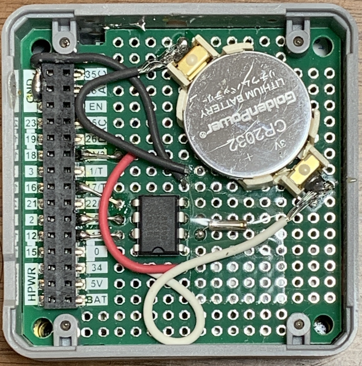
2つ目についてはコイン電池ホルダーをいくつか試し、タカチ電機工業 表面実装型 コイン電池ホルダー SMTUシリーズ の CR2032 用 ならば入ったのでそれを利用した。 Proto モジュール内部で許容される高さはだいたい 5.5 mm ぐらいっぽい(上のホルダーは 5.4 mm)。
下に配線図と実際の写真を載せる。めちゃめちゃ汚い配線だが許容した。

いろいろなところからコードをお借りしてガッチャンしてとりあえず動くコードを書いた。
#include <M5Stack.h>
#include <DS1302.h>
// DS1302 用のモジュールを https://github.com/msparks/arduino-ds1302 からダウンロードして使用可能にしておく。

#define incPin 39                   // (+) Inc. button
#define decPin 38                   // (−) Dec. button
#define entPin 37                   // Enter button


// Timer function: https://lang-ship.com/blog/work/esp32-timer/
hw_timer_t * timer = NULL;
void IRAM_ATTR onTimer() {
  // M5 LCD の左上のカーソル位置は (0, 0) で、右下のカーソル位置は (312, 232) である。
  // 1文字の大きさが (6,8) であることと液晶サイズが (320,240) であることとに依拠していると思われる。
  // これをはみ出していたら clear する。
  if (M5.Lcd.getCursorX() >= 320 || M5.Lcd.getCursorY() >= 240) {
    M5.Lcd.clear();
    M5.Lcd.setCursor(0,0);  // https://lang-ship.com/reference/unofficial/M5StickC/Tips/M5Display/
  }
}


// DS1302
// https://github.com/msparks/arduino-ds1302/blob/master/examples/set_clock/set_clock.ino を改変。

namespace {

// Set the appropriate digital I/O pin connections. These are the pin
// assignments for the Arduino as well for as the DS1302 chip. See the DS1302
// datasheet:
//
//   http://datasheets.maximintegrated.com/en/ds/DS1302.pdf
const int kCePin   = 17;  // Chip Enable
const int kIoPin   = 5;  // Input/Output
const int kSclkPin = 13;  // Serial Clock

// Create a DS1302 object.
DS1302 rtc(kCePin, kIoPin, kSclkPin);

String dayAsString(const Time::Day day) {
  switch (day) {
    case Time::kSunday: return "Sunday";
    case Time::kMonday: return "Monday";
    case Time::kTuesday: return "Tuesday";
    case Time::kWednesday: return "Wednesday";
    case Time::kThursday: return "Thursday";
    case Time::kFriday: return "Friday";
    case Time::kSaturday: return "Saturday";
  }
  return "(unknown day)";
}

void printTime() {
  // Get the current time and date from the chip.
  Time t = rtc.time();

  // Name the day of the week.
  const String day = dayAsString(t.day);

  // Format the time and date and insert into the temporary buffer.
  char buf[50];
  snprintf(buf, sizeof(buf), "%s %04d-%02d-%02d %02d:%02d:%02d",
           day.c_str(),
           t.yr, t.mon, t.date,
           t.hr, t.min, t.sec);

  // Print the formatted string to serial so we can see the time.
  M5.Lcd.println(buf);
}

}  // namespace


//曜日を求める。 https://edu.clipper.co.jp/pg-2-47.html
// 0 = 日曜日
int subZeller( int y, int m, int d )
{
    if( m < 3 ) {
        y--; m += 12;
    }
    return ( y + y/4 - y/100 + y/400 + ( 13*m + 8 )/5 + d )%7;
}

Time::Day subZellerForDS1302Library( int y, int m, int d)
{
    switch (subZeller(y, m, d)) {
      case 0:
        return Time::kSunday;
      case 1:
        return Time::kMonday;
      case 2:
        return Time::kTuesday;
      case 3:
        return Time::kWednesday;
      case 4:
        return Time::kThursday;
      case 5:
        return Time::kFriday;
      case 6:
        return Time::kSaturday;
    }
}


// 時計の設定。 http://radiopench.blog96.fc2.com/blog-entry-923.html を改変。

char buff[10];                     // 文字列操作バッファ
String yymmdd = "yyyy/mm/dd";      // 年月日文字列
String hhmmss = "hh:mm/ss";        // 時分秒文字列
int yy, mo, dd, hh, mi, ss;        // 時刻の要素

void getDateTime(){                // RTCに値を読む、日時の文字列を作成する
  int x;
  yymmdd = "";
  hhmmss = "";
  Time t = rtc.time();

  x =  t.yr%100;           // 年
  yy = x;
  sprintf(buff, "20%02d", x);      // 20に続いて右詰め2桁、1桁なら先頭にゼロ
  yymmdd += buff;

  x = t.mon;            // 月
  mo = x;
  sprintf(buff, "/%02d", x);       // / に続けて右詰め2桁
  yymmdd += buff;
  x = t.date;            // 日
  dd = x;
  sprintf(buff, "/%02d", x);       // / に続けて右詰め2桁
  yymmdd += buff;                  // 年月日の文字列完成(ex:2019/02/28)

  x =  t.hr;           // 時
  hh = x;
  sprintf(buff, "%02d", x);        // 右詰め2桁
  hhmmss += buff;
  x = t.min;            // 分
  mi = x;
  sprintf(buff, ":%02d", x);       // : に続けて右詰め2桁、
  hhmmss += buff;
  x = t.sec;            // 秒
  sprintf(buff, ":%02d", x);       // :に続けて右詰め2桁
  hhmmss += buff;                  // 時分秒の文字列完成(ex:01:02:03)
}

void oledDisp2Chr(int x, int y, int val) {  // OLEDの指定場所に2桁の値を表示
  sprintf(buff, "%02d", val);               // データーを10進2桁0フィル文字列に変換
  M5.Lcd.setCursor(x, y);                     // カーソルを指定位置に合わせて
  M5.Lcd.print(buff);                         // 数値を書き込み
}

int oledRW(int x, int y, int d, int stepD, int minD, int maxD) { // OLEから値を入力
  // OLEDの指定位置に2桁右詰めで変数の値を表示。ボタン操作で値を増減し、
  // Ent入力で値を確定し戻り値として返す。表示位置の左上をx, y 座標で指定
  // 操作位置は下線で表示。値は上下限の範囲でサーキュレート。文字サイズは2倍角(12x16画素)
  // 引数:x座標、y座標、変更したい変数、変更ステップ量、下限値、上限値

  oledDisp2Chr(x, y, d);                    // 画面の指定位置に数値を2桁表示(下線付き)
  while (digitalRead(entPin) == LOW) {      // enterボタンが押されていたら離されるまで待つ
  }
  delay(30);
  while (digitalRead(entPin) == HIGH) {     // enterボタンが押されるまで以下を実行

    if (digitalRead(incPin) == 0) {         // + ボタンが押されていたら
      d = d + stepD;                        // x を指定ステップ増加
      if (d > maxD) {                       // 上限超えたら下限へサキュレート
        d = minD;
      }
      oledDisp2Chr(x, y, d);                // 画面の指定位置に数値を2桁表示(下線付き)
      while (digitalRead(incPin) == 0) {    // + ボタンが離されるまで待つ
      }
      delay(30);
    }

    if (digitalRead(decPin) == 0) {         // - ボタンが押されていたら
      d = d - stepD;                        // x を指定ステップ減らす
      if (d < minD) {                       // 下限以下なら上限へサーキュレート
        d = maxD;
      }
      oledDisp2Chr(x, y, d);                // 画面の指定位置に数値を2桁表示(下線付き)
      while (digitalRead(decPin) == 0) {    // - ボタンが離されるまで待つ
      }
      delay(30);
    }
  }
  delay(30);
  return d;                                 // 戻り値
}

void clockAdjust() {                        // OLEDとボタンスイッチで時刻を合わせる
  M5.Lcd.println("Clock adj.");               // 時刻合わせ開始表示

  while (digitalRead(entPin) == LOW) {      // entボタンが離されるまで待つ
  }
  getDateTime();                            // 現在時刻を取得

  M5.Lcd.clear();                           // 画面を消して
  M5.Lcd.setCursor(0, 0);
  M5.Lcd.println(yymmdd);                     // 現在の年月日を表示

  hhmmss[6] = '-';                          // 秒の桁に--を表示
  hhmmss[7] = '-';
  M5.Lcd.setCursor(13, 16);                   //  (表示位置要調整)
  M5.Lcd.println(hhmmss);                     // 時刻表示

  // x, y座標, 値, ステップ, 下限, 上限を指定して時計の設定値を入力
  yy = oledRW(12,  0, yy, 1, 0, 40);        // 年の値を入力
  mo = oledRW(30,  0, mo, 1, 1, 12);        // 月の入力
  dd = oledRW(48,  0, dd, 1, 1, 31);        // 日の入力。存在しない日(ex:2/31)も入力可能だが動作は不定
  hh = oledRW(13, 16, hh, 1, 0, 23);        // 時 (表示位置要調整)
  mi = oledRW(31, 16, mi, 1, 0, 59);        // 分 (表示位置要調整)

  // Initialize a new chip by turning off write protection and clearing the
  // clock halt flag. These methods needn't always be called. See the DS1302
  // datasheet for details.
  rtc.writeProtect(false);
  rtc.halt(false);

  // Make a new time object to set the date and time.
  // Sunday, September 22, 2013 at 01:38:50.
  Time t(2000+yy, int(mo), int(dd), int(hh), int(mi), 0, subZellerForDS1302Library(2000+yy, mo, dd));

  // Set the time and date on the chip.
  rtc.time(t);
}


void setup() {
  // put your setup code here, to run once:
  M5.begin();

  // Mute Speaker Noise: https://asukiaaa.blogspot.com/2020/03/m5stack-disable-speaker.html
  M5.Speaker.begin();
  M5.Speaker.mute();

  // Set ESP32 Timer: https://lang-ship.com/blog/work/esp32-timer/
  timer = timerBegin(0, 80, true);
  timerAttachInterrupt(timer, &onTimer, true);
  timerAlarmWrite(timer, 1000000, true);  // us
  timerAlarmEnable(timer);


  if (digitalRead(entPin) == LOW){ // 起動時にEnt.ボタンが押されていたら
    clockAdjust();                 // OLED画面と押しボタンを使って時刻合わせ。
  }

}

void loop() {
  // put your main code here, to run repeatedly:
  printTime();
  delay(1000);
}
ふつうに起動するとずっと現在時刻を表示しつづける。ボタンC(一番右のボタン)を押しながら電源を入れると時計設定モードに入ることができる。
Misc
Proto モジュール、GND を引き出すことが想定されてないとしか思えない配置でつらい。
はじめは PCF8523 という IC を使用しようと思ったが、この IC の i2c address 0x68 と M5Stack Gray に標準搭載されている MPU9250 の i2c address 0x68 がぶつかってしまい使用不可であった。
ちなみに M5Stick-C ならば RTC がビルトインされているようだ。M5Stack にも載せてくれればよかったのに。
2021-08-16 追記
M5Stack 用 RTC モジュール基盤が Switch Science で販売されている。IC は PCF8563 で、I2C アドレスは 0x51 のようであり MPU9250 とのアドレス衝突もなさそう。